
Panacea-BOCAF On-Line University
下記の文章は、『Ravi Cell(英語45ページPDF)』の解説をしているサイトhttp://h2o0il.com/の翻訳です。
詳しく読みたい方は、PDFをダウンロードして読んでください。
Research Paper on Ravi’s Water Fuel cell Replication
[Stanley Allen Meyer Page 27]
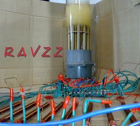
Above is a picture of the multiple bifilars Ravi tried on the WFC. These were connected to each pipe individually. Diode used 1200 V 40 Amps. Solid core length 8" wound with 0.711 mm conductor end to end. The generation increased by approximately another 10cc of gas for a 20 second period compared to regular wound inductors. This works on efficiency!! Need to try out other combos to see if it can increase some more.
下は、WFCにおいてラビが試した複数のバイファイラーの写真です。 これらは個別に各パイプに接続されました。 ダイオードは1200V-40Aを使用しました。 芯(フェライト棒磁石)は長さ8インチ(203.2mm)で、0.711mm径のエナメル線で巻かれています。 インダクターを使用する事で、使用しないときに比べ、常時、約10cc/20secのガスの増加が得られました。 これは効率に影響します! より発生を増加できるかを確認するために、他の組合せを色々と試す必要がありそうです。
[Stanley Allen Meyer Page 28-32]

Variable resistors
Ravi also experimented with using Nichrome 80/20 Resistance Alloy wire in 1.6 mm diameter as the variable resistor. This has resistance of 0.52 Ohms/mt. The efficiency of the cell comes down initially. Ravi states that “if I dont use it for about three to four days but about ten to fifteen minutes after its switched on it gets back to the higher efficiencies”.
ラビ氏は、また、可変の抵抗器として1.6mm直径のニクロム線(NiCr 80/20) を抵抗として実験を行なった。[ニクロム線:ニッケルとクロムを中心とした合金で作られたもの。ニクロム線は電気抵抗が大きくて高温に強く耐久性があるため電熱線として広く利用されている。たとえば、ドライヤー、電気コンロや電気ストーブなどのヒーターとして、ニクロム線は使われている。] これは0.52Ω/mの抵抗を持っています。 セルの効率は、抵抗を入れることで下がります。「実験ですので、約3~4日間は使用してませんが、抵抗をつけた約10~15分後には、より高い効率に戻ります。」と、ラビ氏が述べています。
If you go through Stan's patent 4,798,661 on page2 Figure 1 these variable resistors are designated by the numbers 60a to 60n which are individually connected to each of the inner tubes. Ravi has not tried the immersed exciter array in figure 1 this could probably increase the efficiency even more!
スタン氏の特許#4,798,661[http://www.freepatentsonline.com/4798661.pdf]で見るならば、2ページFigure 1により示され、これらの可変の抵抗器は、チューブのうちのそれぞれと個々に接続される60aから60nまでになると思われます。ラビ氏は、たぶん効率をもっと増大できただろうFigure 1でのEXCITER ARRAY(37番)を沈めることを、試みませんでした![EXCITER:励磁機(れいじき)、励振器(れいしんき) 励磁:コイルに電流を通じて磁束を発生させること。励振:小さな振幅の刺激によって、大きな振幅の振動が引き起こされること。また、引き起こすこと。]

Stan's patent #4,798,661 on page2 Figure 1
Connecting the unit to an ICE
The main reason why Ravi wanted to free source this process was to be used for vehicles as this unit cannot / would not be allowed to be sold commercially as it can give you at least 50% gain in mileage! This would reduce the world’s automobile pollution problem drastically. Power generation through an ICE is not that feasible due to the high wear pertaining to automobile engines when used continuously for months together. As per Ravi’s calculations the engine needs a re-bore every two months if used continuously!!. So the only viable alternative is to use in small Turbines. For backup gensets, IC Engines could be OK. When connecting to an ICE there are a lot of minor to major modifications and tune ups need to be done depending on the engine type and /year of make.
ラビ氏が技術を公開したかった主な理由は、自動車の燃費における最低50%の向上を与えることができるので、このユニットを商業的に売ることが許されないためです! これは世界の自動車公害(排気ガス問題)を大幅に減らします。ICE(Internal Combustion Engine:内燃機関)から発電する方法は、何カ月も絶え間なく継続的に使用されると、自動車用エンジンは多くの摩耗が起こるため現実的ではありません。ラビ氏の計算によると、もし継続的に使われるならば、2ヶ月毎にエンジンをOH(オーバーホール)する必要があるようです。従って、唯一の実行可能な選択肢は、ガスタービンエンジンを使う方法です。バックアップ発電において、IC Engines(Internal Combustion Engine:内燃機関)の採用は、OKかもしれません。内燃機関への装着は、エンジンの大小様々な変更が必要となり、さらに、エンジンのタイプと、製造年に応じて調整される必要があります。
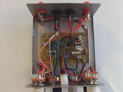
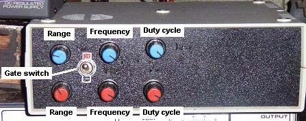
Frequency Generator
Front view

Rear view


Front view

Rear view


Panacea’s first test cell
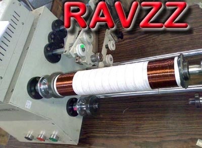
Variable inductor
Ravi is trying some variable inductor Concepts.
ラビ氏は、様々な可変インダクタ構想を試しています。

[Stanley Allen Meyer Page 33-34]
Faculty information
Solid state version
Ravi advises that if the FETS in your signal generator are blowing, the best option would be to alienate the freq gen by introducing the VIC in between. Go through Stan’s US Pat 4936961 for the construction details of the VIC. All that is required are the inductors and a torroid to be wound as per the patent. Ravi states to use larger diameter wires and a larger torroid to avoid heating up of the windings. Also use a high speed 600-1200V 40 Amp diode in between the positive of the inductor and the toroid’s secondary. Problem solved!
ラビ氏は、もし信号発生器のFETSが逝くようならば、最良の選択肢は、中間にVIC(電圧-電流変換器)を導入することによって周波数発生を避けることであるとアドバイスします。VICの構成を確認するために、スタン氏の特許#4,936,961[http://www.nogw.com/download2/-9_meyer_water_electrolysis2.pdf]に目を通してください。ラビ氏は、コイルの発熱を避けるために、より大きい直径ワイヤと、より大きいトロイドの使用を述べてます。また、トロイダルコイルの2次側とインダクタの(+)極との間に、高耐圧・高速ダイオード 600~1200V/40Aを使用してください。 解決された問題!

Originally Dave’s 100 turn inductors were actually made from this VIC description. He did only the inductors and left out the torroidal and the diode. The torroid is the one that isolates the frequency generator and steps up the voltage. Ravi reports that he has already tested it and it improved the gas generation even more.
元々、デイブ氏の100回巻きのインダクタも、このVICの記述により作られました。彼は、トロイダルとダイオードを省略してインダクタだけを使用しました。トロイドは、周波数発生と電圧上昇とを分離するものです。ラビ氏は、既にトロイダルとダイオードの追加をテストし、それがガス発生をさらに改善したと報告します。
Faraday calculations
Calculating 2.4 Watts x 1 hour long applied / liter. 2.4 Watt hours of energy per Liter. That’s multiplied with the hour not divided by the hour.
水素は、1リットル当たり、2.4W/hourのエネルギーです。
Volts x Amps = Watts
12 x 0.51 = 6.12 watts [投入エネルギー]
The generation is around 7 cc/sec of H2 + O2
H2 + O2のガスの発生が7cc/sec、その2/3が水素ガス(4.66cc)
This converts to 4.66 CC of H2/sec which converts to 16.776 Lits / hour 16.776 x 2.4 watts (Faraday/lit/hour generation) = 40.262 Watts. Ravi seems to be generating the equivalent of 40.2 watts as per Faraday with just 6.12 Watts. This would mean he is generating 550% excess as the above works out to 40.2/6.12 x 100 = 656.86%656.86 - 100 (Faraday) = 556.86% OU !!
これは、4.66cc(水素)/sec→16.776L/hour、16.776 x 2.4 watts (Faraday/lit/hour generation) = 40.262 W。ラビ氏は、6.12Wの投入エネルギーで、40.2W分の水素ガス発生を得られた計算になります。分解効率は、40.2W(発生)÷6.12W(投入)x100(率) = 656.86% これは、656.86%-100%(投入)=556.86%、550%以上の過剰なガス発生が得られたことを意味します!!
Presently the approximate volumetric gas discharge by an inverted measuring flask is given below:
逆さにした計量フラスコによる、放出ガスの容積測定結果を以下に示します:
INPUT--H2+O2 cc/sec----H2 only cc/sec-----H2 L/hour
0.5 A-----7.00--------------4.66-------------16.776
1.0 A-----8.66--------------5.78-------------20.808
1.5 A-----11.66-------------7.78-------------28.008
2.0 A-----14.00-------------9.33-------------33.588
3.0 A-----16.36------------10.91-------------39.276
4.0 A-----18.00------------12.00-------------43.200
H2+O2 was calculated on an average basis for collection time of 30 secs. I'm not very sure of H2 and O2 volumes as I've calculated H2 as 2/3rd the volume of the total and O2 as 1/3rd the volume. Incase im wrong please do let me know how to calculate these.
水素+酸素(混合ガス)量は、30秒間の平均収集量に基づいて算出された。水素と酸素の量は、別々に測定したのではなく、発生した混合ガスにおいて水素2/3、酸素1/3の比率で導き出しました。間違っていた場合、どのようにこれらを計算するかを知らせてください。
The gas collected was over 150CC could be 160 / 165CC. As some might say that there could be Steam / Vapour / Mist lets just take the output as 150CC in 20 Secs. This comes to 7.5CC of gas/Sec at 0.48A - 0.50A. Last I checked with the old leads was 7.0 CC gas without any thing removed from the generation.This video shows the voltage input and the amps in both digital and analogue meters. One part of the pulse circuit was switched off (left side 555 in the D14 with the switch on pin 3) and you can see that the current draw is over four fold.
収集されたガスは、150ccより多く160/165ccであるかもしれない。いくつかの可能性をいうと、湯気/蒸気/霧が、150cc/20secのガス発生に含まれているかも知れません。これは、0.48A-0.50Aの投入で、7.5cc/cecのガス発生になります。最後に、私は古いリード(銅に変更する前のステンレス導線仕様)によってチェックしました、7.0ccのガス発生でした。下記の動画は、デジタルテスターで電圧入力を、アナログメーターで使用アンペアを見せています。パルス回路の1つの部分のスイッチが切られ(D14回路における左側IC555のピン3のスイッチ)、その後、使用電流が4倍を超えている事に気づくと思います。[パルス回路の効果を証明していると思われます]
NEXT>>Water Fuel Cell Voltrolysis Replication No.5
http://ameblo.jp/ghostripon/entry-10350465759.html
■過去記事
Water Fuel Cell Voltrolysis Replication No.1
http://ameblo.jp/ghostripon/entry-10346485209.html
Water Fuel Cell Voltrolysis Replication No.2
http://ameblo.jp/ghostripon/entry-10347229739.html
Water Fuel Cell Voltrolysis Replication No.3
http://ameblo.jp/ghostripon/entry-10349626443.html
■関連記事
Pulsed Water-splitters No.1(パルスを用いた水の分解)
http://ameblo.jp/ghostripon/entry-10330994478.html
Stanley Meyer Data特許資料(英文) [pdf 221ページ]
http://www.free-energy-info.co.uk/MeyerData.pdf
Stanley Meyer - It Runs On Water(水で走る自動車)
http://ameblo.jp/ghostripon/entry-10328859717.html
【資料】Stanley Meyer - It Runs On Water(水で走る自動車)
http://ameblo.jp/ghostripon/entry-10330431267.html
【資料2】Stanley Meyer - It Runs On Water(水で走る自動車)
http://ameblo.jp/ghostripon/entry-10342515816.html
各セル構造の比較&検証(パルスを用いた水の分解)
http://ameblo.jp/ghostripon/entry-10335356396.html