Author: Patrick J. Kelly
Chapter 10: Automotive Systems No.2
http://www.free-energy-info.co.uk/Chapt10.html

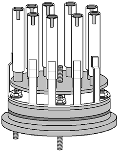
A ring of nine evenly-spaced inner pipes are positioned around the edge of a steel disc which is slightly smaller than the inside dimension of the acrylic tube. The pipes appear to be a tight push-fit in holes drilled very accurately through the disc. These holes need to be exactly at right-angles to the face of the disc in order for the pipes to be exactly aligned with the acrylic tube ? definitely a drill-press job. The disc is mounted on a central threaded rod which projects through the plastic base disc, and a plastic spacer is used to hold the disc clear of the studs positioned at ninety degrees apart around the outer edge of the base disc.
9つのインナーパイプが等間隔に配置され、アクリルパイプ(容器)の中の内径より少し小さいステンレスディスクにはまります。 インナーパイプは、ステンレスディスクに開けられた精密な穴にしまりばめで固定されるようです。 これらの穴をディスクに対し、正確かつ垂直にあけるのは、インナーパイプがアクリルパイプと平行になるように配置する必要がある?ボール盤やフライスでやるべき作業。(現在ならレーザーカットでも良さそう) ディスクの中央は、スタッドボルトとスペーサーによりマウントされ、スペーサーはディスクとインナーチューブがアクリルパイプと平行になるよう固定するために使用されます。(中央一点止めのようです)
The mounting for the outer tubes is also most unusual. A piece of steel plate is cut with nine projecting arms at evenly-spaced positions around a circular washer shape as shown here:
外側のチューブ用の取り付けもとても珍しいです。スチールプレートはカットされ均等かつ等間隔に9つの突出する腕をもっています、ここに示す:

This piece has four holes drilled in it to match the stud positions of the plastic base piece. The number of studs is not specified and while I have shown four, the plate resonance might be helped if there were just three. The size is arranged so that when the arms are bent upwards at right-angles, they fit exactly against the inner face of the acrylic tube.
このプレートには、プラスチック製ベースに対応する4つのスタッド用の穴が開けられています。スタッドの数は本来指定されていないが、私は4つで示している。板共振をより発生させたい状況なら3つでも良いだろう。プレートの腕の角度は、ベースから垂直に立ち上がり、全てがアクリルパイプと平行に曲がって配置されます。
These arms get two bends in them in order to kink them inwards to form mounts for the outer tubes. The degree of accuracy needed her is considerable as it appears that there are no spacers used between the inner and outer tubes. This means that the very small gap of 1.5 mm or so has to be maintained by the accuracy of these mounts for the outer tubes.
これらの9つの腕は、アウターチューブのマウントを形成するために、さらに2箇所を曲げてます。 曲げの角度は、個々に正確さが必要で、スペーサー無しでインナーチューブとのクリアランス(ギャップ)が約1.5mmであることを考えると、アウターチューブを固定するのにどの程度精度が必要か理解できるでしょう。
It should be noted that the inner tubes are much longer than the outer tubes and that the outer tubes have a tuning slot cut in them. All of the inner tubes are mechanically connected together through their steel mounting disc and all of the outer tubes are connected together through the ring-shaped steel disc and its kinked arm mounts. It is intended that both of these assemblies should resonate at the same frequency, and they are tuned to do just that. Because the inner tubes have a smaller diameter, they will resonate at a higher frequency than a larger diameter pipe of the same length. For that reason, they are made longer to lower their natural resonant frequency. In addition to that, the slots cut in the outer tubes are a tuning method which raises their resonant pitch. These slots will be adjusted until every pipe resonates at the same frequency.
アウターチューブよりも、インナーチューブが長く、アウターチューブにはチューニングスロットをカットしている点に注意すべきです。すべてのインナーチューブは機械的にステンレスディスクに固定され、アウターチューブはカットされたスチールプレートと、屈折したアームにより固定されます。これは、インナーチューブとアウターチューブ両方のアセンブリが、同じ周波数で共鳴するように意図しチューニングされている。これは、インナーチューブは直径が小さいので、同じ長さの大口径管よりも高い周波数で振動します。その理由で、インナーチューブは周波数が下がるように長めに作られています。それに加えて、アウターチューブにあけるスロットは、振動周波数を高く発生させるためのチューニング方法です。すべてのパイプは、同じ周波数で共鳴させるためスロットにより微調整されます。
Looking initially at the mechanical design, suggests that the assembly is impossible to assemble, and while that is almost true, as it will have to be constructed as it is assembled and it appears that the inner and outer pipe assembly can’t be taken apart after assembly. This is the way they are put together:
注視 機能面で、インナーアウターを個々に組み立てたものを単純に組み合わせる方法では、狙った共鳴が発生しないことを示しておきます。なぜなら、組立中に個別に調整される必要があり、組立後に、インナーおよびアウターパイプアセンブリを分解してしまうと調整が狂うので分解不可。以上、組立方法です:
The ring support for the outer pipes is not bolted securely to the plastic base but instead it is spaced slightly above it and mounted on just the stud points. This ring is underneath the slightly smaller diameter disc which holds the inner pipes. This makes it impossible for the two components to be slid together or apart, due to the length of the pipes. This suggests that either the inner pipes are pushed into place after assembly (which is highly unlikely as they will have been assembled before for tuning) or that the outer pipes are welded to their supports during the assembly process (which is much more likely).
アウターパイプのリングサポートはプラスチック製のベースに直接ボルトで固定されるのではなく、代わりに、それはプラスチック製のベースからわずかに間隔をあけた状態で、スタッドボルトにより固定されます。(下の断面図を参考に)このリングは、インナーパイプを保持している少し小さいディスクの下に固定される。長いインナーパイプにアウターパイプが重なり同じベースに固定されるため、2つのコンポーネントが、一緒にまたは離れて脱落することがなくなります。これは、インナーパイプがアセンブリの後にステンレスディスクに圧入されるか、またはアウターパイプが、インナーパイプの組立後、サポートに溶接されることを示します。
One of the “studs” is carried right through the plastic base in order that it can become the positive connection of the electrical supply, fed to the outer pipes. The central threaded rod is also carried all the way through the plastic base and is used to support the steel plate holding the inner pipes as well as providing the negative electrical connection, often referred to as the electrical “ground”.
「スタッド(ボルト)」のうちの1本は、プラスチック製ベースを通り抜けて電源供給のポジティブ【+極】として外部と接続される。中心のスタッド(ボルト)もまた、プラスチック製ベースを通り抜けて、インナーパイプを保持するディスクを固定するためだけでなく、ネガティブ【-極】な電気接続を提供するために使用されます。多くの場合、配線図では「グラウンド(GND)」と呼ばれます。
Another plastic disc is machined to form a conical lid for the acrylic tube, having a groove to hold an O-ring seal and the water inlet for refilling and the gas output tube. The drawing mentions the fact that if tap water is used, then the impurities in it will collect in the bottom of the electrolyser when the water is removed by being converted to hydroxy gas. This means that the cell would have to be rinsed out from time to time. It also draws attention to the fact that the gasses dissolved in the tap water will also come out during use and will be mixed with the hydroxy gas output.
上部のプラスチックのディスクは、水の補充とガスのアウトプット管接続のため穴が開けられ、アクリルパイプ(容器)とのシールを保つためのためのOリング用溝を持っている。内側は、円錐形のふたを形成するために加工されます。図面は、水道水が使われることに言及し、そして、水が水素混合ガスに変換されることで取り除かれる時には、その不純物は電解槽の底に集まります。これは、セルを時々すすぐ(掃除する)必要があることを意味しています。また、実際に注意しなければならないことは、使用の間に不純物がガスとして出て、水素混合ガスのアウトプットと混ぜられる可能性があることです。
When these various components are put together, the overall cell construction is shown like this:
これらのさまざまなコンポーネントが組み立てられる時には、全体のセル構造は、このように示されています:

This cross-sectional view may be slightly misleading as it suggests that each of the nine outer pipes has its own separate bracket and this is probably not the case as they are connected together electrically through the steel ring-shaped disc and should vibrate as a single unit. It is tempting to use separate brackets as that would allow the assembly to be taken apart quite easily, but the electrical contacts of such a system would be much inferior and so it is not to be recommended.
9本のアウターチューブは、個々にアームで固定され、スチールプレートを通して一緒に電気的に接続され、一つの部品として同時に振動するべきであるので、上の断面図は少し紛らわしい示唆になるかもしれません。図が、アセンブリを容易に分解できるように見せるように、上の断面図は、別個のブラケットで固定しているように見せる。そのようなシステムの電気的に接続はとても劣るので、従って、それは推奨できません。
Because of the way that all of the inner pipes are connected together and all of the outer pipes are connected together electrically, this form of construction is not suited to the three-phase alternator drive shown below, where the nine pipes would have to be connected in separate sets of three. Instead, the solid-state circuit is used, which is very effective and which does not have the size, weight, noise and increased current of the alternator arrangement.
インナーパイプのうちのすべてが接続、およびアウターパイプのすべてが接続される方法のため、この構造は、下に示された3相の交流発電機ドライブに適していません。その場合、9本のパイプが、3本づつ3ユニットにおいて接続される必要がある。 代わりに、ソリッドステート回路が使用されます。(非常に効果的であり、サイズ、重さ、ノイズ、および交流発電機による増大する電流がない)
If accuracy of construction is a problem, then it might be possible to give the outer pipes a deliberate slope so that they press against the inner pipes at the top, and then use one short spacer to force them apart and give the desired spacing. It seems clear that Stan worked to such a degree of constructional accuracy that his pipes were perfectly aligned all along their lengths.
もし構造の精度に問題があるならば、アウターパイプをインナーパイプに押し当て、そのあと、はなすことにより故意にクリアランスの調整をすることが可能で、要求されたクリアランス(ギャップ)を与えることが許されます。スタン氏が、パイプの長さと角度が揃うように、構造上の精度調整に取り組んでいたのは、明確に見てとれます。
Dave Lawton points out that the connection point of the brackets for the outer pipes is highly critical as they need to be at a resonating node of the pipes. The connection point is therefore at 22.4% of the length of the pipe from the bottom of the pipe. Presumably, if a slot is cut in the top of the pipe, then the resonant pipe length will be measured to the bottom of the slot and the connection point set at 22.4% of that length. Dave Lawton’s pipe arrangement can be driven either via an alternator or by an electronic circuit. A suitable circuit for the alternator arrangement is:
デイブロートン氏は、接続ポイントが、パイプの共鳴の節になる必要があるのでアウターパイプ固定のためのブラケットの接続ポイント(高さ)が非常に重要であると指摘します。従って、接続ポイントはパイプの底からパイプの長さの22.4%に位置します。もしスロット(切欠き)がパイプのトップあるならば、接続ポイントは、そのスロット(切欠き)の下端から底までの長さの22.4%でセットされるべきである。デイブロートン氏のパイプ接続配置は以下で、交流発電機を経て、また電子回路により動かされます。交流発電機配置に適当な回路は下記です:

In this rather unusual circuit, the rotor winding of an alternator is pulsed via an oscillator circuit which has variable frequency and variable Mark/Space ratio and which can be gated on and off to produce the output waveform shown below the alternator in the circuit diagram. The oscillator circuit has a degree of supply de-coupling by the 100 ohm resistor feeding the 100 microfarad capacitor. This is to reduce voltage ripple coming along the +12 volt supply line, caused by the current pulses through the rotor winding. The output arrangement feeding the pipe electrodes of the electrolyser is copied directly from Stan Meyer’s circuit diagram.
この珍しい回路において、交流発電機のコイルの回転は、可変の周波数と可変のMark/Space比率を持ち、回路図の交流発電機の下で示されたアウトプット波形を生み出すため、出力時、断続的にコントロールされ、発振器回路を経てパルス化されます。発振回路の電源には、ある程度、電子デバイスが発生する電源雑音や,それに伴う放射電磁雑音(EMI)を抑える目的で、100Ωの抵抗体と100μFコンデンサを使用してます。これは、コイルの回転を通した現在のパルスによって引き起こされた、+12ボルトの電源に乗って来るリップル(「さざ波」ある一定の電圧の上に乗っている小さなさざ波の様な電圧)電圧を減少させるためのものです。電解槽のパイプ電極に供給している出力配置は、直接スタン・マイヤー氏の回路図からコピーされました。
It is not recommended that you use an alternator should you decide to build a copy of your own. But if you decide to use one and the alternator does not have the windings taken to the outside of the casing, it is necessary to open the alternator, remove the internal regulator and diodes and pull out three leads from the ends of the stator windings. If you have an alternator which has the windings already accessible from the outside, then the stator winding connections are likely to be as shown here:
あなたが、このシステムの複製品を自作するなら、交流発電機を使用する方法はお勧めできません。しかし、もし交流発電機(オルタネーター)を使うと決めた場合、ケースの外にコイルがないならば、交流発電機を分解することが必要です。内部のレギュレーターとダイオードを取り除き、固定子巻線の端から3つのリードを引き出してください。もしケースの外にコイルがあり、すでに得やすい巻線を持っている交流発電機を持っているならば、固定子を巻いている接続は、ここに示されたとおり:

The motor driving Dave’s alternator draws about two amps of current which roughly doubles the power input to the circuit. There is no need for the size, weight, noise, mechanical wear and current draw of using a motor and alternator as pretty much the same performance can be produced by the solid-state circuit with no moving parts.
デイブ氏の交流発電機(オルタネータを動かすモーター)の駆動電流は、おおよその回路への電源入力の2倍、約2A消費します。モーターと交流発電機とほとんど同じ機能を、サイズ、重量、ノイズに優れ、機械的消耗(可動部品)がない、ソリッドステート・リレー(半導体を使った無接点リレー、高速高頻度動作が可能)で代用できるので、いまさらモーターと交流発電機を使うことの必要性が全くありません。
Both circuits have been assessed as operating at anything from 300% to 900% of Faraday’s “maximum electrical efficiency”, it should be stressed that the inductors used in this circuit, form a very important role in altering and amplifying the voltage waveform applied to the cell. Dave uses two “bi-filar wound” inductors, each wound with 100 turns of 22 SWG (21 AWG) enamelled copper wire on a 9 mm (3/8”) diameter ferrite rod. The length of the ferrite rod is not at all critical, and a ferrite toroid could be used as an alternative, though that is more difficult to wind. These bi-filar coils are wound at the same time using two lengths of wire side by side. The solid-state circuit is shown here:
両方の回路について、Michael Faraday氏(England 1791–1867)の理論では、「maximum electrical efficiency(最大の電気効率)」において300%~900%で動作すると評価されている。この回路においてインダクタ(コイル、巻線などにおいて電流の変化が誘導起電力となって現れる)が使われたことは強調されるべきである。非常に重要な役割として、セル(電極チューブ)が、電圧波形(直流パルス)を増幅する点が上げられる。デイブ氏は、9mm(3/8インチ)直径フェライト棒に、それぞれ22SWG = 0.711mm(サイズ21AWG)エナメル塗装銅線を、100回転「バイファイラー巻き」で巻いたインダクタを使います。フェライト棒の長さは、重要ではない。そして、代替手段としてフェライト・トロイダルを使用することができました、それは巻き上げするのが、より難しいのですが。バイファイラーコイルは、同時に2つワイヤを並べて巻かれます。ソリッドステート回路は以下に示されます:


Circuit operation:
回路の動作:
The main part of the circuit is made up of two standard 555 chip timers. These are wired to give an output waveform which switches very rapidly between a high voltage and a low voltage. The ideal waveform shape coming from this circuit is described as a “square wave” output. In this particular version of the circuit, the rate at which the circuit flips between high and low voltage (called the “frequency”) can be adjusted by the user turning a knob. Also, the length of the ON time to the OFF time (called the “Mark/Space Ratio”) is also adjustable.
回路の主要な部分は2つの標準555チップタイマーにより構成されています。 これらは、高い電圧と低電圧とを非常に急速に切り換えた出力波形を得るために使用されています。 この回路から来る理想的な波形形は、「矩形波」アウトプットと評されます。 このバージョンの回路では、回路の電圧の高低(以下、"周波数" と呼ばれる)を、ユーザーがノブを回して調整することができます。 また、オフ時間(以下、"マーク /スペース比")のオン時間の長さも調整可能です。

感想:
交流発電機を使用する方法(回路)は、お勧めできないと言う事ですね。
スタンレー・メイヤー氏の理論にもベースがあって、文中の記述に突如現れた、
Michael Faraday氏(England 1791–1867) が元のようですね。
そう考えると、200年越しの技術か・・・ 感慨深いですね。
フィーリング意訳について、気になる点は、原文を確認してください。
(その為に、原文も載せてます)
次回は、各回路の説明です。
Pulsed Water-splitters No.3(パルスを用いた水の分解)
http://ameblo.jp/ghostripon/entry-10332022863.html
■前回の記事
Pulsed Water-splitters No.1(パルスを用いた水の分解)
http://ameblo.jp/ghostripon/entry-10330994478.html
■関連記事
Stanley Meyer Data特許資料(英文) [pdf 221ページ]
http://www.free-energy-info.co.uk/MeyerData.pdf
Stanley Meyer - It Runs On Water(水で走る自動車)
http://ameblo.jp/ghostripon/entry-10328859717.html
【資料】Stanley Meyer - It Runs On Water(水で走る自動車)
http://ameblo.jp/ghostripon/entry-10330431267.html
原子水素ガス - HHO GAS - ブラウン・ガス -
http://ameblo.jp/ghostripon/entry-10323958738.html
【続】原子水素ガス - HHO GAS - ブラウン・ガス -
http://ameblo.jp/ghostripon/entry-10328872198.html
燃える塩水 - Salt Water -
http://ameblo.jp/ghostripon/entry-10323134471.html
Byron New Energy - チャージ水 - charged water -
http://ameblo.jp/ghostripon/entry-10324533613.html