Creating a FIR Filter Channel Divider [4] (Hardware @ SPDIF→DSP→DAC Edition)
Items needed:
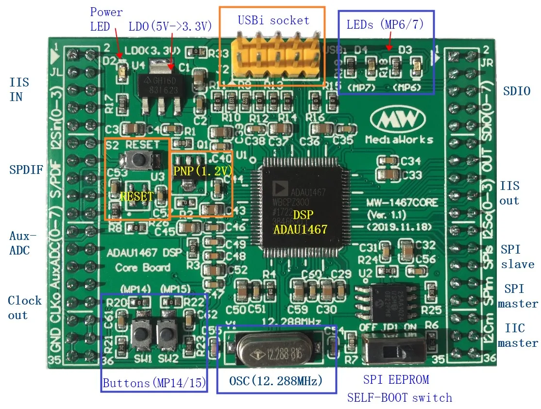
For more details, please refer to this link.
- ADAU1467 board
- USBi (programming tool)
- SPDIF board (WM8805)
- DAC board (PCM5102A)
- A suitable breadboard (for power relay wiring)
In addition, you'll need:
- A Windows computer
- A device capable of outputting optical or coaxial SPDIF
- An oscilloscope (not recommended, but you can also use an amp and speaker setup that you don't mind potentially damaging)
Wiring materials
For the wiring, you'll need a combination of male-to-male and male-to-female connectors.

Having a set of materials like this is convenient:
Power wiring
For the above:
- ADAU1467 board
- SPDIF board (WM8805)
- DAC board (PCM5102A)


SPDIF
Next, we'll connect the input side, specifically the I2S.
Connect the SPDIF output to the I2S input 0 channel (xxxxi0) of the ADAU1467 board.
SPDIF → ADAU1467
- LRCK → LRCKi0
- SDAT → SDATi0
- BCK → BCKi0

By the way, the pin designations may vary:
- LRCK can be labeled as LRCLK
- BCK can be labeled as BCLK
- SDAT can be labeled as SDATA
- Keep this in mind.
DAC
For the DAC, follow the same procedure as the SPDIF:
Connect the ADAU1467 board's I2S output 0 channel (xxxxo0) to the DAC's input.
DAC ← ADAU1467
- LRCK ← LRCKo0
- SDAT ← SDATo0
- BCK ← BCKo0

When you connect the SPDIF and DAC, it should look like this.

USBi
To connect to SigmaStudio (DSP design software), connect the USBi.
On the surface of the ADAU1467, there are 10-pin terminals where you'll connect it.
Just be careful about the orientation of the cable.

oscilloscope
To verify the output signal, let's also connect an oscilloscope.
I've made a rather forced connection to the audio output section of the DAC.

Try supplying power
Try connecting the USBi to your computer.
The ADAU1467 board and the LED on the DAC board should light up.
If the LED doesn't light up at this point, immediately disconnect the USB and double-check the wiring.
※ If your connected computer displays messages like USB not recognized, don't worry about it here (it should not be displayed if SigmaStudio is installed).
First, with this, the preparation is complete.