Shenzhen, China, May 9, 2019 − Gigalight announced that its 5G OMUX for a Chinese operator successfully passed the interoperability test with Huawei's 5G fronthaul equipment, fully complying with the construction requirements of the 5G project.
Gigalight’s 5G OMUX
The 5G OMUX products that have passed the test mainly provide the functions of multiplexing and demultiplexing the wavelengths of the fronthaul signals, including the LAN-WDM (LWDM) channels carrying 5G services and the CWDM channels carrying 4G services. Gigalight adopts a professional and mature WDM technology platform to control the insertion loss within 0.5dB. The other product indicators are also excellent. Gigalight’s 5G OMUX is one of the best solutions for the C-RAN architecture with concentrated service wavelengths in the 5G fronthaul network, and saves operators much cost of optical fiber resources.
Targeting the global scale commercial 5G in 2020, Gigalight actively explores and studies the application standards of 5G optical interconnects, and has shipped 5G passive and active modules on a global scale. The networking test of Gigalight's 5G OMUX with Huawei's 5G fronthaul equipment further proves the interoperability of Gigalight products in the 5G field.
About Gigalight
Gigalight is a global optical interconnection design innovator that designs, manufactures and supplies optical transceivers, passive components, active optical cables, MTP/MPO cablings, cloud programmers & checkers, and coherent optical modules etc. for three main applications: Data Center & Cloud Computing, Metro & Broadcast Network, and Wireless & 5G Optical Network. Gigalight takes the advantages of exclusive design to provide customers with one-stop optical network devices and cost-effective products.
The growing role of clouds in data communications of all kinds with the consequent growth of hyperscale data centers, small moves towards 400Gbps deployment. There are some debates about which one is optimal for the Next-Generation Data Center (NGDC)? AOC or DAC?
First, how well do you know the optimal high-speed optical solutions for NGDC?
Distance
Cost
Power consumption
Cable weight
Density
Latency
DAC
DAC, short for Direct Attach Cable, is used to connect one mobility access switch with another when forming a stack. DAC can be either Passive Copper Cable (PCC) or Active Copper Cable (ACC).
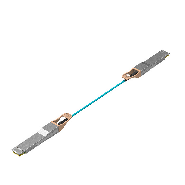
AOC
AOC, short for Active Optical Cable, is an alternative to optical transceivers. It eliminates the separable interface between the transceiver module and optical cable and offers a number of advantages over DAC. Here is a picture of AOC as following.
AOC vs. DAC
AOC features longer distance—DAC up to 15m; AOC up to 300m.
DAC is cheaper than AOC.
DAC features lower power consumption than AOC.
AOC features lower cable weight than DAC.
DAC and AOC offer the same density.
AOC features lower latency than DAC.
Conclusion
As the development of optical communication technologies, it is said that the optics will replace copper in the future. Thought I don't think so, there is no doubt that AOC is becoming the mainstream solution for NGDC owing to its advantages. AOC will have a greater potential than DAC in the deployment of NGDC.
A few years ago, the largest data centers would never have bought Chinese AOCs fearing that they would be low quality. There are data center managers who worry about such things and are very rigid about specs when it comes to components such as AOCs. However, with the development of optical communication market in recent years, the whole AOC business is shifting to China. We expect that the differences between the U.S. and Chinese firms are eroding when it comes to quality. As one of the best Chinese firms, Gigalight is respectable in the AOC market. In 2019, Gigalight can offer 200Gbps and even 400Gbps AOCs.
As a popular signal transmission technology for high-speed signal interconnection in Next-Generation Data Center (NGDC), PAM4 technology is widely used for electrical or optical signal transmission on 200G/400G interfaces. This article will take you through the full understanding of PAM4 technology.
What Is PAM4
PAM4, short for 4-Level Pulse Amplitude Modulation, is a kind of PAM technology that uses 4 different signal levels for signal transmission. Each symbol period can represent 2 bits of logic information (0, 1, 2, 3), that is, four levels per unit time.
When it comes to PAM4 signal transmission technology, it is necessary to mention NRZ (Non-Return-to-Zero). NRZ is the most traditional digital signal, that is, using high and low signal levels to represent the 1/0 information of the digital logic signal can transmit 1 bit of logic information per signal symbol period.
The figure below is a comparison of the typical PAM4 and NRZ signal waveforms and eye diagrams.
Compared to NRZ, PAM4 has four digital amplitude levels, each of which contains two information bits, and at the same baud rate, the throughput is twice that of NRZ.
Why PAM4?
The rapid development of the network era has brought about a higher demand for network transmission rates.
Generally, there are three ways to increase the optical communication transmission rate:
Increase the modulation rate.
Increase the number of WDM channels
Increase the number of levels
PAM4 technology can effectively improve the bandwidth utilization efficiency. At the same time, PAM4 adopts high-order modulation format, which is an effective way to reduce the number of optical devices used, reduce the performance requirements of optical devices and performance, cost and work in different applications. A balance is reached between consumption and density.
The arrival of big data and cloud computing, the growth of traffic, the urgent need for a more complex modulation method, PAM4 is a more efficient modulation technology.
In the development of the new generation of 200G/400G interface standards, the general appeal is that the data rate on each pair of differential lines should be increased to more than 50Gbps. If NRZ technology is still used, the use of PAM4 technology is almost an inevitable trend because the time margin for transceiver chips and transmission links is more demanding because each symbol period is less than 20ps.
The Basis of PAM4
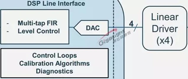
Generally, the technologies for implementing PAM4 are classified into two types, namely, a DSP-based digital DAC implementation method or a simulation-based combine method.
The mainstream analog mode is based on MSB & LSB combiner to implement PAM4 signal, and there are two NRZ signals for adding operation.
The mainstream digital approach is based on a high-speed DAC for fast output at 0/1/2/3 levels.
At the same time, PAM4 compared with NRZ, the challenges it faces in the design and testing process can not be ignored.
The Challenges of PAM4
The PAM4 signal has 16 switching states, the middle eye is symmetrical, and the upper and lower eye patterns are asymmetrical. In an optical eye diagram, the linearity of the optical device is very poor, or the linearity of the driving of the laser is very poor. The upper and lower eye diagrams of the PAM4 are easily deformed, and the deformation is easily misjudged. The parameters of the test, such as jitter, eye width, eye height is not accurate.
Although the PAM4 signal reduces the symbol rate of the signal, the channel loss of more than 10dB still makes the eye diagram of the receiving end completely closed. Therefore, for the PAM4 signal, the pre-emphasis of the transmitting end and the signal equalization of the receiving end are also important.
Compared to NRZ, the Signal-to-Noise Ratio (SNR) of PAM4 is reduced by 9.6dB, so in most cases, the PAM4 system (without FEC) will not operate without errors: BER=ERFC(SQRT(SNR)).
In most PAM4 scenarios, there is no possibility that the system will run without errors. IEEE 802.3 specifies the pre-FEC BER indicator for the PAM4 system.
At present, the product of the DSP scheme is BER<1E-7 before the actual FEC. The current product of the simulation scheme is BER<1E-6 before the actual FEC. In fact, the requirement to ensure that no large block error occurs is prior to the BER parameter.
All of the PAM4 products from Gigalight can be divided into two categories from the solution:
Digital PAM4 Products—DSP Solutions. The DSP can support a variety of complex and efficient modulation methods. The electric port has strong adaptability and good photoelectric performance.
Analog PAM4 Products—Analog CDR Solutions with low power consumption and low cost.
Gigalight always adheres to the concept of innovation, innovative technology, and overcomes difficulties. It invests a lot of human resources and material resources in the research and development of next-generation data center products, and aims to provide effective solutions for the development of next-generation data centers.
PAM4 (4-Level Pulse Amplitude Modulation) is one of PAM modulation technologies that uses 4 different signal levels for signal transmission. Each symbol period can represent 2 bits of logic information (0, 1, 2, 3), that is, four levels per unit time.
In the data center and short-distance optical fiber transmission, the modulation scheme of NRZ is still adopted, that is, the high and low signal levels are used to represent the (1, 0) information of the digital logic signal to be transmitted, and one bit of logical information can be transmitted per signal symbol period.
However, as the transmission rate evolves from 28Gb/s to a higher rate, the electrical signal transmission on the backplane will cause more severe loss to the high-frequency signal, and higher-order modulation can transmit more data in the same signal bandwidth. Therefore, the industry is increasingly calling for higher-order PAM4 modulation. The PAM4 signal uses four different signal levels for signal transmission, and each symbol period can represent 2 bits of logical information (0, 1, 2, 3). Since the PAM4 signal can transmit 2 bits of information per symbol period, to achieve the same signal transmission capability, the symbol rate of the PAM4 signal only needs to reach half of the NRZ signal, so the loss caused by the transmission channel is greatly reduced. With the development of future technologies, the possibility of using more levels of PAM8 or even PAM16 signals for information transmission is not ruled out.
And then, if the optical signal can also be transmitted by using the PAM4, the clock recovery and pre-emphasized PAM4 signal can be directly realized when the electro-optical transmitting is performed inside the optical module, therefore, the unnecessary step of converting the PAM4 signal into the NRZ signal of 2 times the baud rate and then performing related processing is eliminated, thereby saving the chip design cost.
Why PAM4?
The end-to-end transmission system includes fiber optic and fiber-optic transmission systems. Since the fiber transmission can easily reach the rate of 25Gbd so that the research progress of transmitting PAM4 on the fiber has been progressing slowly. For fiber-optic transmission systems, from NRZ moving to PAM4 is considered in terms of cost. If you do not need to consider the cost, there are other related modulation technologies can be used in the long-distance range, such as DP-QPSK, which can transmit the baud rate signal above 50Gbd for several thousand kilometers. However, in the data center field, the transmission distance is generally only 10km or less. If the optical transceiver using PAM4 technology is adopted, the cost can be greatly reduced.
For 400GE, the largest cost is expected to be optical components and related RF packages. PAM4 technology uses four different signal levels for signal transmission. It can transmit 2 bits of logic information per clock cycle and double the transmission bandwidth, thus effectively reducing transmission costs. For example, 50GE is based on a single 25G optical device, and the bandwidth is doubled through the electrical layer PAM4 technology, which effectively solves the problem of high cost while satisfying the bandwidth improvement. The 200GE/400GE adopts 4/8 channel 25G devices, and the bandwidth can be doubled by PAM4 technology.
For data center applications, reducing the application of the device can significantly reduce costs. The initial goal of adopting higher order modulation formats is to place more complex parts on the circuit side to reduce the optical performance requirements. The use of high-order modulation formats is an effective way to reduce the number of optics used, reduce the performance requirements of optics, and achieve a balance between performance, cost, power, and density in different applications.
In some application scenarios, high-order modulation formats have been used for several years on the line side. However, since the client side needs are different from the line side, so other considerations are needed.
For example, on the client side, the main consideration is the test cost, power consumption and density. On the line side, spectrum efficiency and performance are mainly considered, and cost reduction is not the most important consideration. By using linear components on the client side and the PAM4 modulation format that is directly detected, companies can greatly reduce test complexity and thus reduce costs. Among all high-order modulation formats, the lowest cost implementation is PAM4 modulation with a spectral efficiency of 2 bits/s/Hz.
Conclusion
As a popular signal transmission technology for high-speed signal interconnection in next-generation data centers, PAM4 signals are widely used for electrical and optical signal transmission on 200G/400G interfaces. Gigalight has a first-class R&D team in the industry and has overcome the signal integrity design challenges of PAM4 modulation. Gigalight's 200G/400G PAM4 products include 200G QSFP56 SR4, 200G QSFP56 AOC, 200G QSFP56 FR4, 400G QSFP56-DD SR8, 400G QSFP56-DD AOC, etc.
All of the PAM4 products from Gigalight can be divided into digital PAM4 products and analog PAM4 products. The digital PAM4 products adopt DSP solutions which can support a variety of complex and efficient modulation schemes. The electric port has strong adaptability and good photoelectric performance. And the analog PAM4 products simulate CDR with low power consumption and low cost. Gigalight always adheres to the concept of innovation, innovative technology, and overcomes difficulties. It invests a lot of human resources and material resources in the research and development of next-generation data center products.
A significant portion of Data Center Interconnections (DCIs) and telecom router-to-router interconnections rely on simple ZR or 80km transceivers. The former is mostly based on 100Gbps per 100GHz ITU-T window C-band DWDM transceivers, while the latter is mostly 10G or 100G grey wavelength transceivers. In DWDM links, the laser wavelength is fixed to a specified grid, so that with DWDM Mux and Demux 80 or more wavelength channels can be transported through a single fiber. Grey wavelengths are not fixed to a grid and can be anywhere in the C-Band, limiting capacity to one channel per fiber. DCI links tend to use DWDM because they have to utilize the optical fiber bandwidth as much as possible due to the extremely high-volume traffic between data centers.
Another emerging 80km market is the Multi-System Operator (MSO) or the CATV optical access networks. This need emerges because MSOs are running out of their access optical fibers and they need a transmission technology which would allow them to grow to a very large capacity by using the remaining fibers. For this reason they need to use DWDM wavelengths to pack more channels in a single fiber.
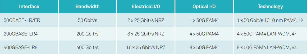
The majority of the 10G transceivers on 80km links will be replaced by 100G or 400G transceivers in the coming years. For that to happen, there are two modulation techniques to enable 80km 100G transceivers.
50G PAM4 with two wavelengths in a 100G transceiver
Generally speaking, PAM4 is a low-cost solution but require active optical dispersion compensation (which could be a big headache as well as extra expense to data center operators) and extra optical amplification to compensate for the dispersion compensators. By contrast, Coherent approaches do not need any dispersion compensation and the price is coming down rapidly, especially when the same hardware can be configured to upgrade the transmission data rate per wavelength from 100G to 200G (by using DP-16QAM modulation).
When 400G per wavelength is needed in a DCI network within a 100GHz ITU-T window, coherent technology is the only cost-effective solution, because it will not be feasible for PAM4 to achieve the same high spectral efficiency of 4 bit/sec/Hz.
On the standards front, many standards organizations are adopting coherent technology for 80km transmission. The Optical Inter-networking Forum (OIF) will adopt coherent DP-16QAM modulation at up to 60Gbaud (400G per wavelength) in an implementation agreement on 400G ZR. This is initially for DCI applications with a transmission distance of more than 80km, and vendors may come up with various derivatives for longer transmission distances. Separately, CableLabs has published a specification document for 100G DP-QPSK coherent transmission over a distance of 80km aimed at MSO applications. In addition, IEEE802.3ct is in the process of adopting coherent technologies for 100G and 400G per wavelength transmissions over 80km.
As data rates increase from 100G to 400G and capacity requirements per fiber are driven by DCI needs, and assisted by volume driven cost reductions in coherent optics and in coherent DSPs, we expect coherent transmission to be the technology of choice for 80km links.